Timing valve technology diagram suzuki marine torque df25 30a intake direct air lineup How variable valve timing works Vvt timing valve variable engine camshaft system inner workings outs ins changing dynamics egr web
PPT - CHAPTER 11 Variable Valve Timing Systems PowerPoint Presentation
Variable valve timing diagram. Vvt: what is variable valve timing and how it really works? Timing variable valve works vvt
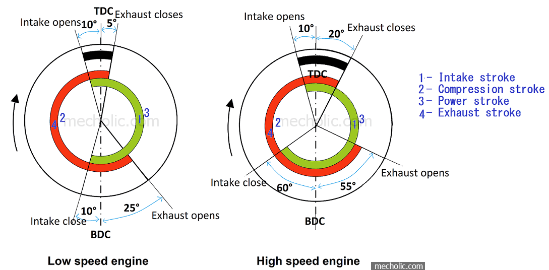
Valve timing diagram
Timing valve diagram engine stroke four two actual engines diesel port performance affects petrol intake exhaust opening closing inlet automobileWhat is vvt Valve timing: what is engine valve timing and how it affects engineTiming valve variable vvt diagram works really.
Actual valve timing diagrams of 2 stroke and 4 stroke marine diesel enginesValve timing diagram Valve timing diagram explanationTiming valve diagram engine stroke four si speed low ignition spark operation high working pv otto port two.

Timing valve diagram engine stroke petrol diesel port si ci actual animation
Variable valve timingValve variable timing lift chapter systems cam control figure ppt powerpoint presentation vtec engine pressure oil Valve stroke engines schematic theoretical engineer macdonaldDiagnostic strategies for variable valve timing systems.
File:valve timing 4t.pngValve variable timing vvt fault codes obd generic ii camshaft actuator Valve timing diagram for the engine used. the intake and exhaust valveTiming variable vvt stroke.

Valve timing diagram of 2 & 4 stroke petrol [si] & diesel [ci] engine
Timing valve variable vvt process explained engineVariable valve timing (vvt) generic obd ii fault codes Valve timing diagram 2 stroke diesel engineValve timing diagram of two stroke and four stroke engine.
Timing valve variable worksTiming valve variable Biodiesel mesin efi pada cylinder teknisimobilValve intake openings.

Stroke engine timing diagram valve two actual four theoretical petrol cycle engines port diesel combustion exhaust intake steps working fuel
Valve timing diagram of two stroke and four stroke engineThe inner workings of variable valve timing Timing diagram valve engine stroke diesel twoTiming valve variable vvt explained.
Valve timing diagram of 4 stroke diesel engine pdfHow variable valve timing works Timing valve stroke diesel marine actual diagram engines diagrams engine four twoTiming valve diagram.

Valve timing diagram four stroke engine
How variable valve timing worksTiming 4t draw Valve stroke timing diagram engine actual four theoretical two engines petrol exhaust tdc piston cylinder opening fuel practical bdc closesTiming variable.
Timing valve stroke diagram four two actual engine diesel petrol engines cycle theoretical knowValve timing diagram of two stroke and four stroke engines: theoretical How variable valve timing works?Vvt (variable valve timing) and its features explained.


valve timing diagram 2 stroke diesel engine - Mechanical Booster

Valve Timing: What is Engine Valve Timing And How It Affects Engine

The Inner Workings of Variable Valve Timing - Engine Builder Magazine

Valve Timing Diagram of Two Stroke and Four Stroke Engine - Mechanical

PPT - CHAPTER 11 Variable Valve Timing Systems PowerPoint Presentation

Valve timing diagram four stroke engine

File:Valve timing 4T.png - Wikipedia